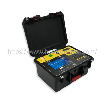
Insulation resistance tester usage and working principle
Insulation resistance testers, often called megohmmeters or megohmmeters, are widely used to measure the insulation of generators, motors, power transformers, wiring, appliances and other electrical devices such as cables for control, signaling, communications and power supplies. resistance. They are often used during routine maintenance procedures to indicate changes in a motor's insulation resistance over months or years. Large changes in insulation resistance may indicate potential failure. Therefore, the megohmmeter needs to be calibrated regularly to ensure that the meter itself has not changed over time.
Working principle of insulation resistance tester:
A megohmmeter uses Ohm's law to measure resistance by stimulating the device or network under test with a voltage and then measuring the current generated by the stimulus. A good megohmmeter calibrator includes a variety of optional resistors, not much different from the resistors provided by modern calibrators using the synthetic resistance feature. Megohmmeter calibrators differ from DC/low frequency calibrators in the resistor range required, as well as the voltage capabilities they can withstand. For example, these electrical testers apply much higher voltages when making resistance measurements than the ohmmeter function found on digital multimeters (DMMs). Megohmmeters typically operate on voltages ranging from 50V up to 5kV; typical digital multimeters typically operate on voltages less than 10V. For insulation testing, the resistance value range that needs to be measured is large, the upper limit can reach 10TΩ, and the required voltage is higher.

Upgrade Your Home: Double Gang European Design Switch Benefits
Mastering 1-Gang Light Switches: Tips & Common Fixes
10 Questions You Should Know about Smart Home Automation Systems
How Does a Smart Home System Work?
Guide to Installing a 3-Gang Light Switch
The Advantages of Implementing 45*45 Modular Socket
Triple Light Switch vs. Single Switch: Which Is Best for You?
Almost all insulation testers use DC voltage as excitation, so a megohmmeter calibrator has very few AC requirements. Many megohmmeters are two-terminal devices that provide a voltage and measure the current determined by the device under test. Megohmmeters with a range of 1TΩ and higher usually have a third terminal, called a guard, which is very useful for eliminating leakage paths and parallel components with unknown resistance Rx being measured. The purpose of the protection terminal is to selectively reduce the impact of output parasitic resistive components to zero by eliminating possible leakage currents.
A major problem when calibrating these instruments is finding suitable resistors, which are of course sufficient first; they also need to be large enough that they can withstand high DC voltages. In addition, megohmmeter manufacturers do not have a uniform standard for what resistance values should be used for calibration, so a variety of resistance values are required. By understanding the different types of insulation testers, you can know that they require different performance checkpoints. For example, one tester needs to test 50kΩ, another tester needs to test 60kΩ, another tester needs to test 100kΩ, and so on.
"General purpose" multifunctional electrical/electronic calibrators cannot be used to calibrate insulation resistance testers because their resistors are usually only capable of handling a limited voltage, often no more than 20V. The challenge for insulation resistance calibrators is to integrate these special needs into an economical, compact and portable solution.
How Will 45*45 Modular Sockets Change Designs?
Ultimate Guide to Miniature Circuit Breaker with Case
Key Questions to Ask When Choosing a Home Security System for Your Property
Maximize Efficiency with Acs355 03u 38a0 4 Solutions
What are the applications of Acs355 03u 24a4 2?
Unlocking Performance: ABB ACS355 03U Insights
Unlocking PCBA OEM: Your Guide to Success


